
Neutron Irradiation
Overview
TRIUMF makes use of three separate locations to perform neutron irradiations. The TNF facility offers energies from Thermal to 400 MeV at high intensity while at BL1B and BL2C, protons can be converted into neutrons yielding 1/E energy spectra up to 480 and 120 MeV, respectively. Each year, companies from around the world test many different types of devices, ranging from avionics to ground-based electronic systems such as network and power-distribution servers, or even the latest cell-phone chips. Neutron flux is monitored with BF₃ counters and dosimetry is regularly performed using activation foils of nickel, aluminum, carbon, and gold. The beam characteristics, sizes and intensities that are available at NIF are summarized below.
TNF Neutrons
The final beam stop on the high-intensity beam line BL1A produces neutrons from the spallation reaction of 100-150 µA of 400 to 450 MeV protons on an aluminum plate absorber surrounded by a water moderator. Neutron channels transport these neutrons through the shielding surrounding the TNF. Initially thermal neutrons were used for a neutron scattering experiment on one of these channels. In 2002 the energy spectrum of these neutrons was measured to determine the greater than 1 MeV neutron component.
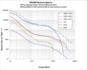
The flux of neutrons at the normal operating currents on BL1A is 6×10⁶ neutrons/cm²/s above 1 MeV, comparable with the neutron flux at the LANSCE neutron radiation-effect line, and has energies extending to about 400 MeV as shown in the neutron spectrum. Thermal neutrons are also present if desired; they can be easily removed using a cadmium shield. Beam specifications are available in this Table.
Access to this neutron beam is available for roughly 3000 hours per year as a symbiotic operation with BL1A. At TNF, the physical space for devices is limited: device size must be smaller than 15 cm thick and 25 cm wide.
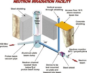
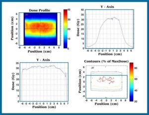
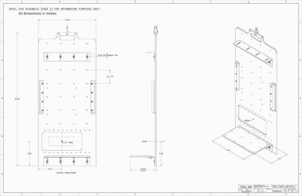
The TNF plan view is shown below and gives the layout of the testing area. There is also a separate counting room available to the users. The neutron beam is accessed from 5 m above the beam through a vertical slot in the shielding. Devices to be tested are mounted on a movable-trolley plate which is then lowered into the neutron beam on a cable. The neutron-beam size obtained using radiochromic film is shown below in the neutron-beam picture. There is no neutron-beam blocker. The device is simply lowered into the beam and then raised out of the beam once the desired fluence is reached.
BL1B and BL2C
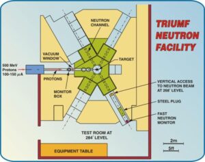
Neutrons can be produced in the present Proton Irradiation Facility (PIF) area by stopping energetic protons from either BL1B or BL2C on a fully absorbing beam stop and setting up downstream of the beam stop. The resulting neutron spectra have a 1/E falloff of flux with energies up to the proton energy. Beam specifications are available in this Table.
The neutron flux and energy spectrum has been measured for different proton energies and a few geometries using a combination of Bonner spheres and carbon-foil activations. These neutrons have already been used to test various types of neutron dosimeters and to check for neutron radiation effects in sensitive electronics.
The sea-level neutron flux is approximated at 20 neutrons/cm²/hr above 10 MeV. The neutron flux produced by stopping 3 nA of 120 MeV protons on a lead absorber, at a location 1.4 m downstream, is about 5×10⁴ neutrons/cm²/s which is approximately 10⁷ times higher than the sea-level neutron flux, allowing rapid testing of electronic components or detectors.
NIF BEAM SPECIFICATIONS
Neutron Energy Spectra
TRIUMF offers three different locations for testing with neutrons. The neutron spectra of the TRIUMF neutron beams are similar to the JEDEC atmospheric neutron reference spectrum, as can be seen in the image below.
Beam characteristics
The beam specifications for each location are given in the table below. The neutron flux is monitored with BF3counters and dosimetry for calibrations is regularly performed using activation foils of nickel, aluminum, carbon, and gold.
|
|
TNF neutrons | BL1B neutrons | BL2C neutrons (no longer in use) |
Energy |
Thermal to 400 MeV |
1/E spectrum to 480 MeV | 1/E spectrum to 120 MeV |
Flux (neutrons/cm²/s)
|
2x10⁶ to 3x10⁶ above 10 MeV 5x10⁵ thermal energies |
10³ to 5x10⁵ above 10 MeV |
10³ to 5x10⁴ above 10 MeV |
| Spot Size |
5x12 cm |
4 to 60 cm diameter |
30 to 150 cm diameter |
| Spot Homogeneity |
+/- 10% |
+/- 10% |
+/- 10% |
| Beam Counting and Monitoring System |
BF₃ Counter and Activation Foils |
BF₃ Counter and Activation Foils |
BF₃ Counter and Activation Foils |
| Device-Positioning System |
Movable Trolley with positive stop |
Remote-controlled X-Y platform with laser alignment |
Remote-controlled X-Y platform with laser alignment |
| Access Conditions |
6 m cable length to Control Area |
20 m cable length to Control Area |
20 m cable length to Control Area |
BL1B NEUTRON BEAM CALCULATOR
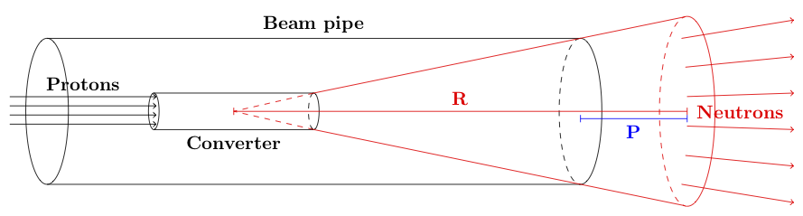
On BL1B, the proton beam is converted into a neutron beam using a cylindrical lead converter, as shown in the schematic. (The schematic is not to scale.)
The resulting neutron beam is cone-like. The diameter of the beam spot and the beam intensity change with the square of the distance R from the neutron converter. Note that R is not the same as P, the distance between the end of the beam pipe and the DUT that is measured in the test room. R is 96 cm longer than P.
If at position R₁, the maximum beam flux is φ₁ (in neutrons/cm²/s) and the beam spot diameter is D₁, then the beam characteristics at position R₂ can be calculated from those at R₁ using the following relationships:
The maximum beam flux φ corresponds to neutron flux that can be achieved using the maximum proton current on BL1B. It is always possible to lower the flux, but not to increase it past this safety limit.
Use the calculators below to plan your tests using the most up-to-date calibrations of the BL1B neutron beams.
I want a neutron beam with a diameter of at least cm.
I want to reach a flux of neutrons/cm²/s.
I want to setup cm from the end of the beam pipe.


Calculator of 1-MeV equivalent neutron fluences
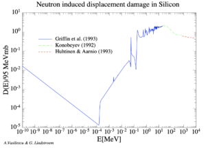
The 1-MeV-neutron equivalent fluence for exposures of silicon components on the beamlines of PIF & NIF is calculated on this page using the method outlined in the ASTM E722-14 standard. The energy-dependent dose damage ratio data used in the calculation is as compiled by A. Vasilescu and G. Lindstroem and shown in this figure:
The full data tables and original figures are available at: https://rd50.web.cern.ch/rd50/NIEL/
Select the beamline spectrum to use for the calculation:
Select the neutron energy range to use in the calculation:
What was the total fluence of >10 MeV neutrons delivered on the beamline during irradiation? n/cm² for neutrons with energy >10 MeV.
CONTACT INFORMATION
For further information, please contact:
| Michael Trinczek TRIUMF Tel: 604.222.7530 Fax: 604.222.1074 |
Camille Bélanger-Champagne TRIUMF Tel: 604.222.7706 Fax: 604.222.1074 |
Alex Hands TRIUMF Tel: 604.222.7628 Fax: 604.222.1074 |