
Proton Irradiation
Overview
The Proton Irradiation Facility (PIF) was designed primarily for single-event effect (SEE) studies and characterization of electronic components and detectors for the space environment. The energy spectrum of protons trapped in earth orbits peaks in the 10-100 MeV region (depending on the amount of intervening absorber) and drops by about an order of magnitude at 500 MeV. This makes the TRIUMF cyclotron’s variable-energy capability of up to 500 MeV ideal for studies of space effects. Biological studies such as cell irradiations to measure the relative biological effectiveness (RBE) of protons are also being carried out in conjunction with the Proton Therapy Centre.
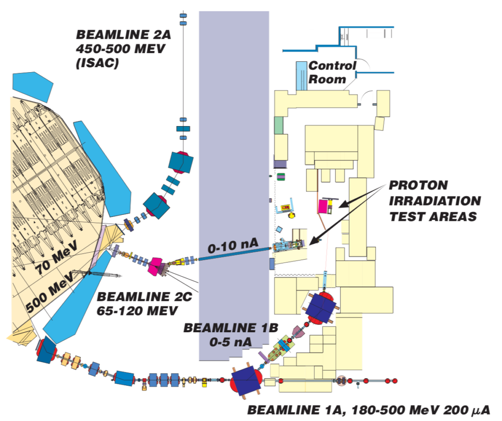
PIF makes use of two different beamlines at TRIUMF for low-intensity radiation-damage studies. The lower energies, variable from as low as 5 MeV up to 120 MeV are available from the beamline BL2C, which is also used on a regular basis for proton treatments of ocular melanoma. Higher energies, from 220 MeV up to 500 MeV are available from a second beam line, BL1B, which transports proton beams into the same experimental area. On both beamlines, beam characteristics are provided by multiple ion chambers, scintillators, and beam-profile monitors. The beam sizes and intensities that are available at PIF are summarized in this Table.
A unique feature of the TRIUMF cyclotron is that it is capable of simultaneously extracting several proton beams of different energies and intensities. This is achieved by accelerating H– ions and using a stripping foil or wire, located at the correct radius in the cyclotron, to extract protons of the desired energy. The intensity is determined by the area of the stripping foil intercepting the beam and is adjusted with the height and shape of the foil.
High-Energy Protons
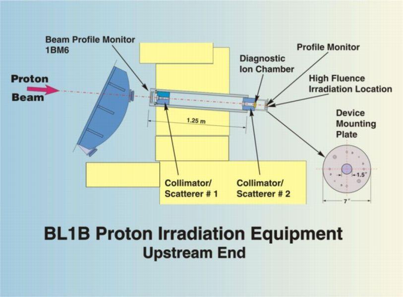
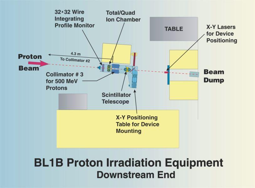
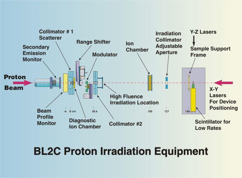
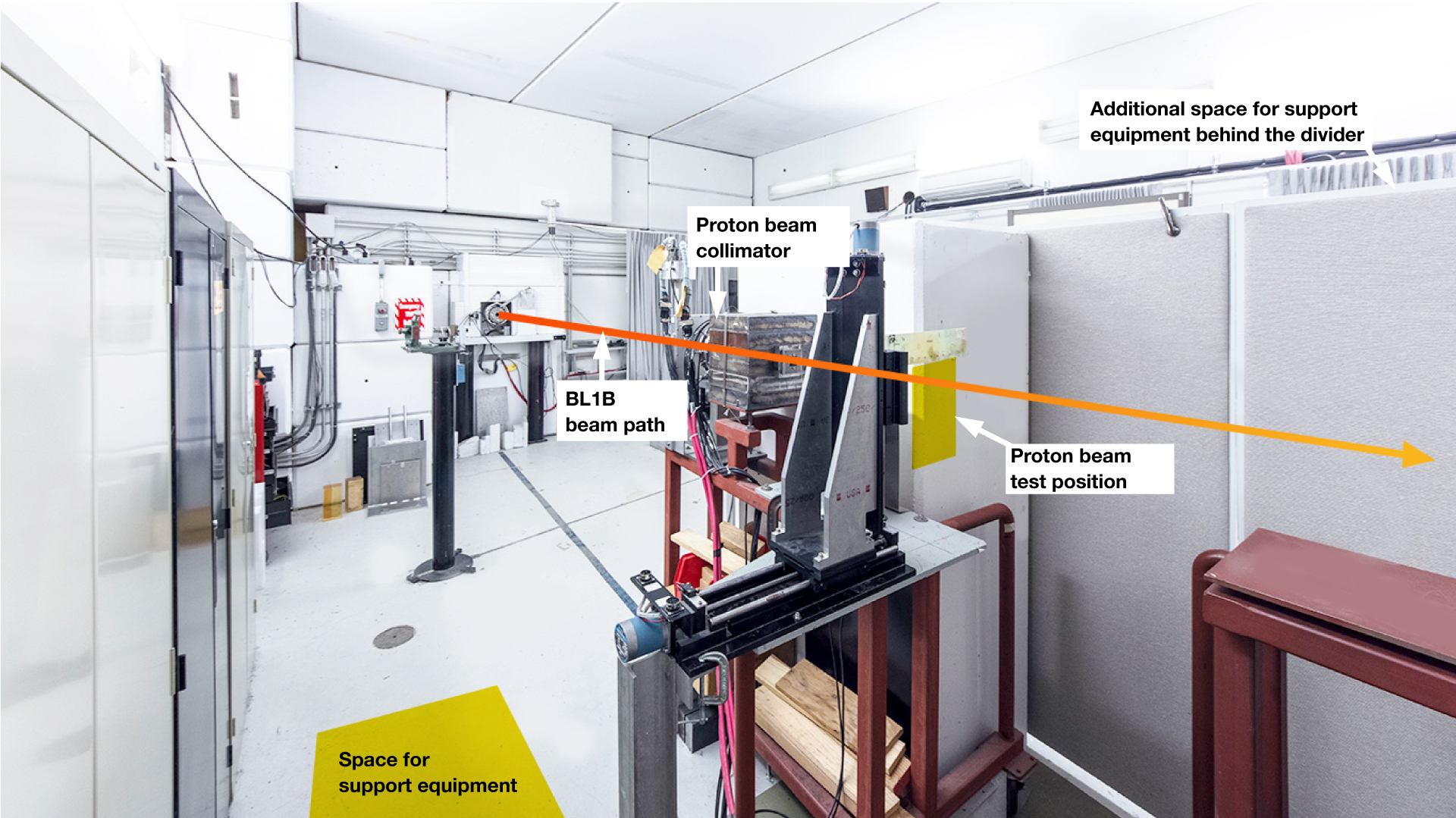
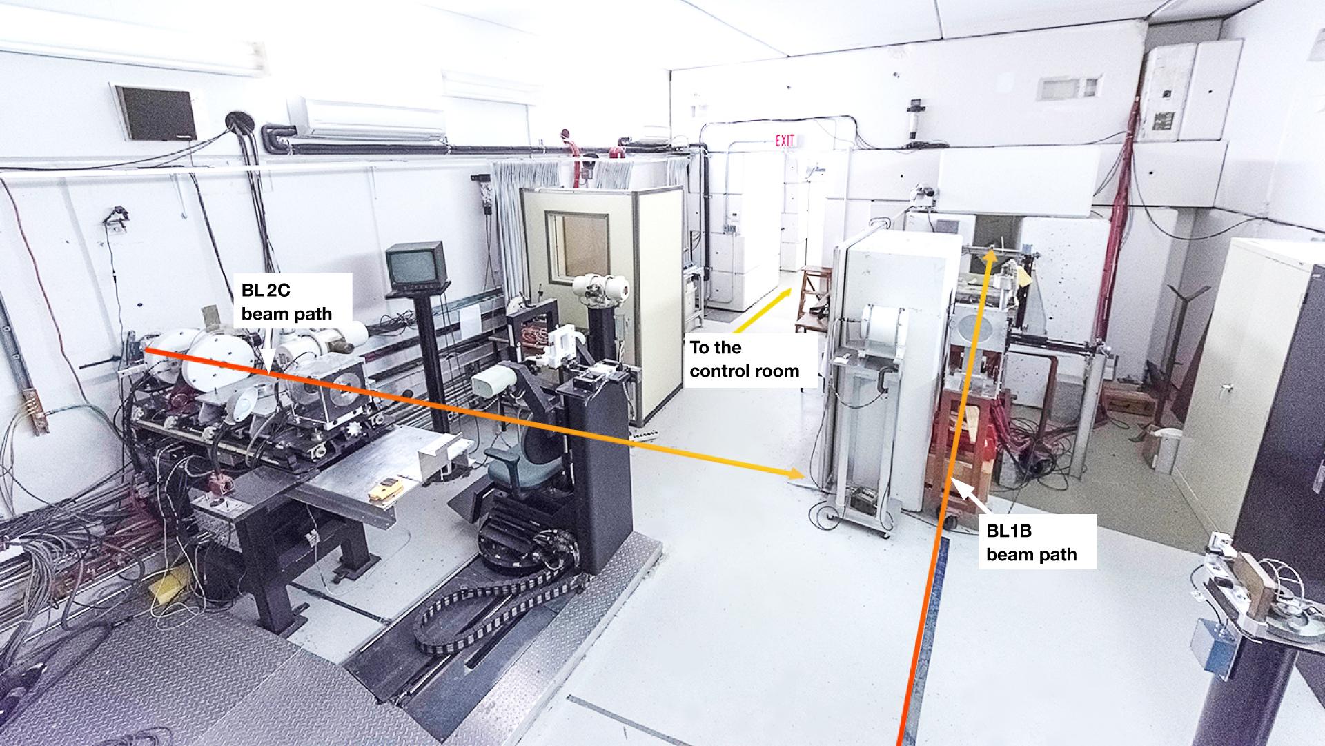
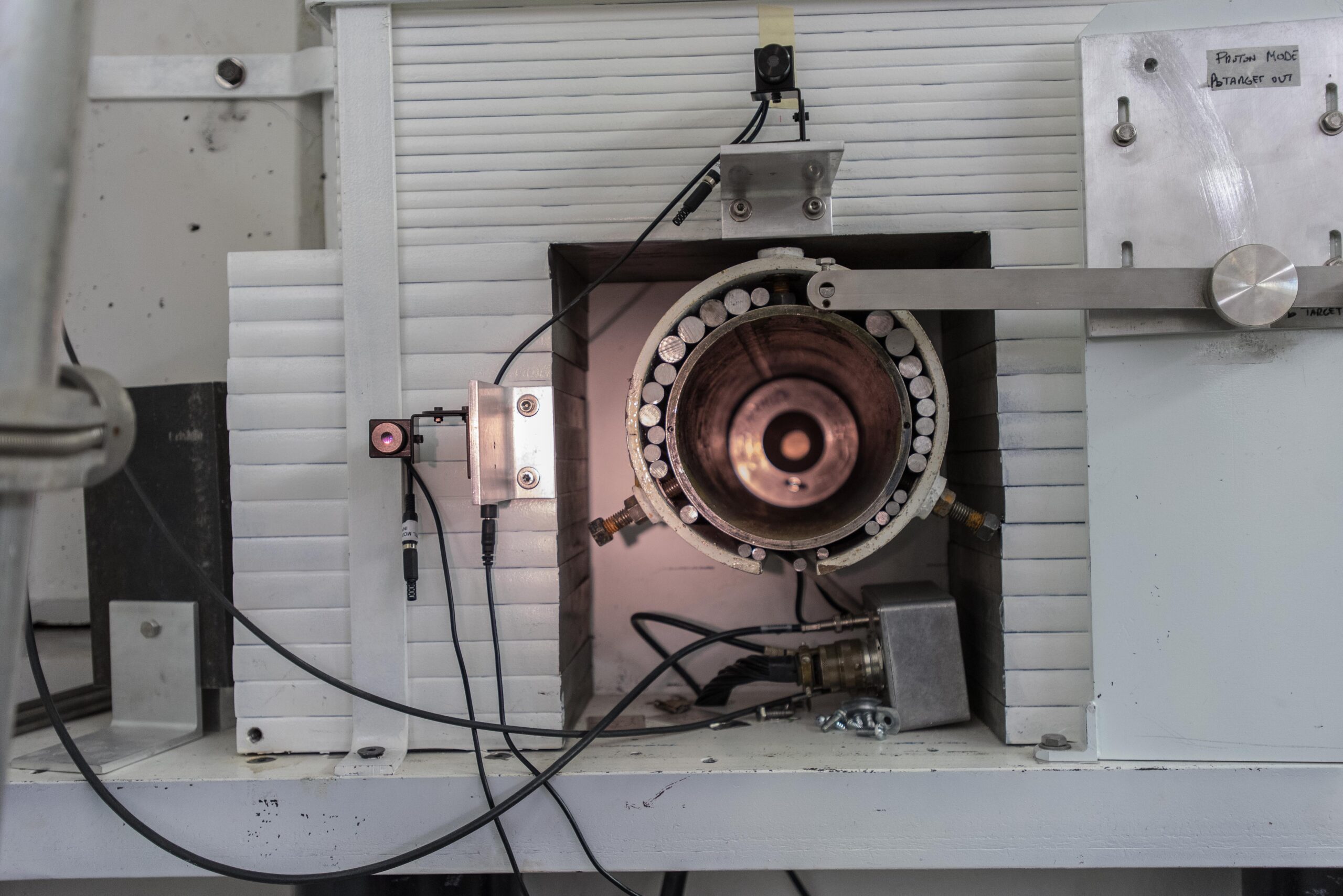
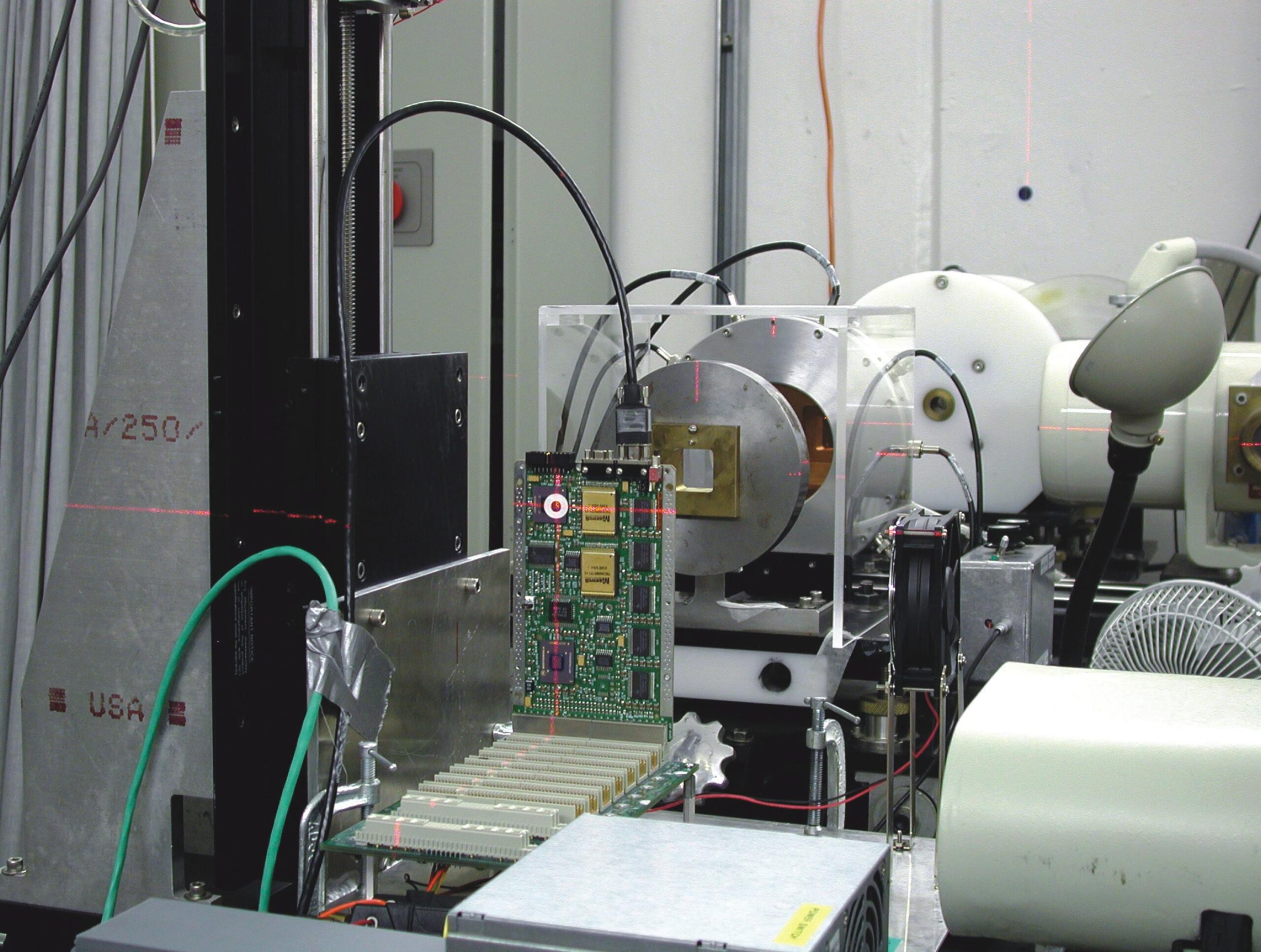
Beam line BL1B is used to transport low-intensity protons with energies from 220 to 500 MeV into the irradiation area; the broad range of available energies and intensities make the BL1B facility unique in the world. The upstream section contains the primary beam collimator and scatterer and has a Front location for higher-flux testing. The downstream section contains the beam-diagnostic equipment, the X-Y table for device positioning, and the beam-defining (spot-size) collimator for the Back location. Beam specifications are available in this Table.
The extraction system for BL1B is shared with BL1A and is normally available for PIF use only when low-intensity beam is circulating in the cyclotron.
Low-Energy Protons
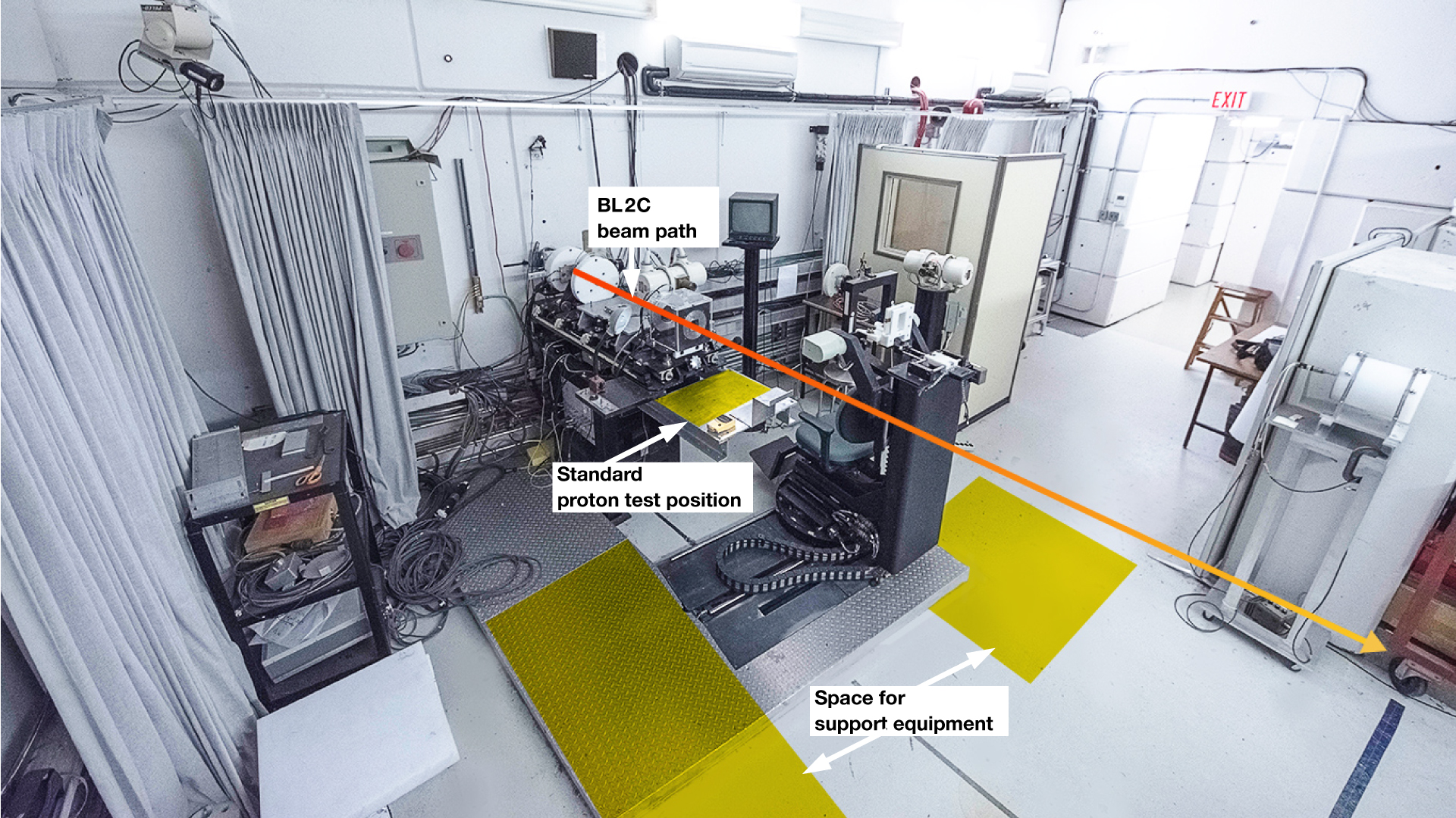
Entering the same experimental area is the lower-energy beam line BL2C which provides protons with energies available from 5 to 120 MeV. To get energies below the cyclotron’s lowest extracted energy of 65 MeV, material is placed in the way of the beam to degrade the energy. The energy spread of the proton beam after the degrader will be greater than the 1 to 2 MeV FWHM of the incident beam due to straggling and this can be calculated for the specific situation.
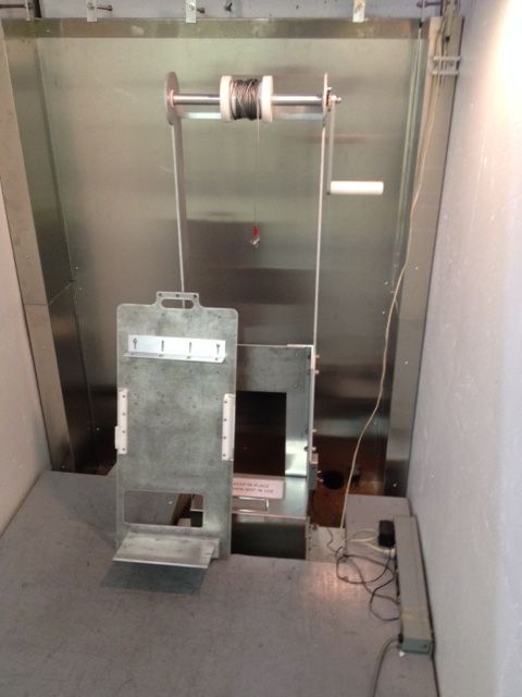
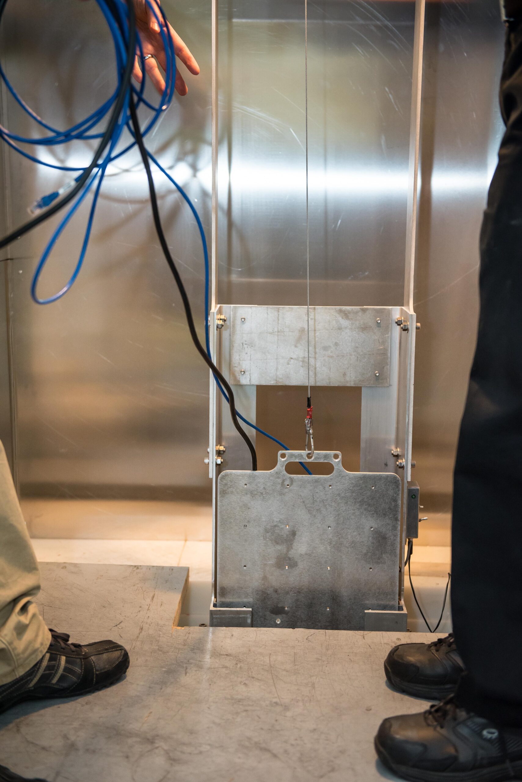
Once again, there are two testing locations: The standard Back location with an X-Y table for device positioning, and laser alignment and a higher-fluence Front location. Beam specifications are available in this Table.
In both energy regimes, low-intensity neutron beams can also be obtained by stopping the protons in a full-energy beam stop and setting up downstream of the beam stop; please see the Neutron Irradiation Facility (NIF) page for details. This beam line is also used for Proton Therapy, where a modulated 74-MeV proton beam is used to treat ocular melanomas. This beamline is scheduled for use one week per month and is thus available more frequently then the high energy beamline.
PIF BEAM SPECIFICATIONS
For testing with proton beams at both high and low energy, TRIUMF offers two standard configurations. The Standard location features the most uniform beam and is typically used for most irradiations, but an Upstream location is available for higher intensities, though over a smaller area. Specifications are given in the table below.
Extracted-beam energy changes are performed by the Cyclotron operators in the Main Control room and are usually accomplished in under 30 minutes. Degrader changes are done remotely by the user.
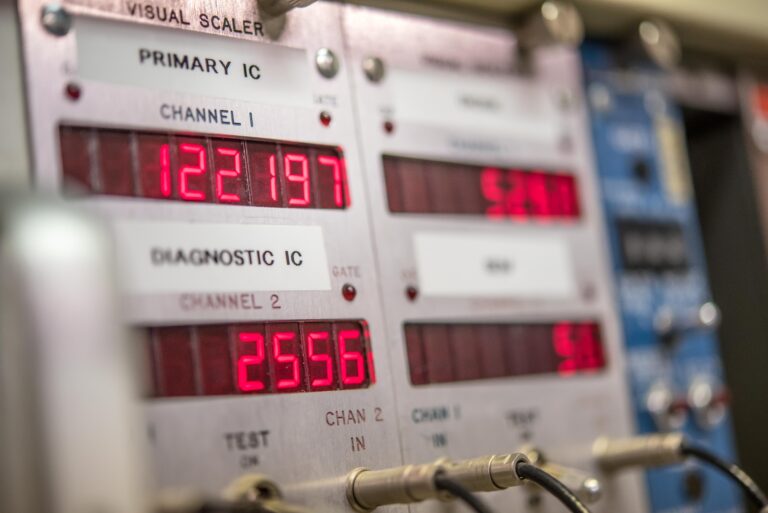
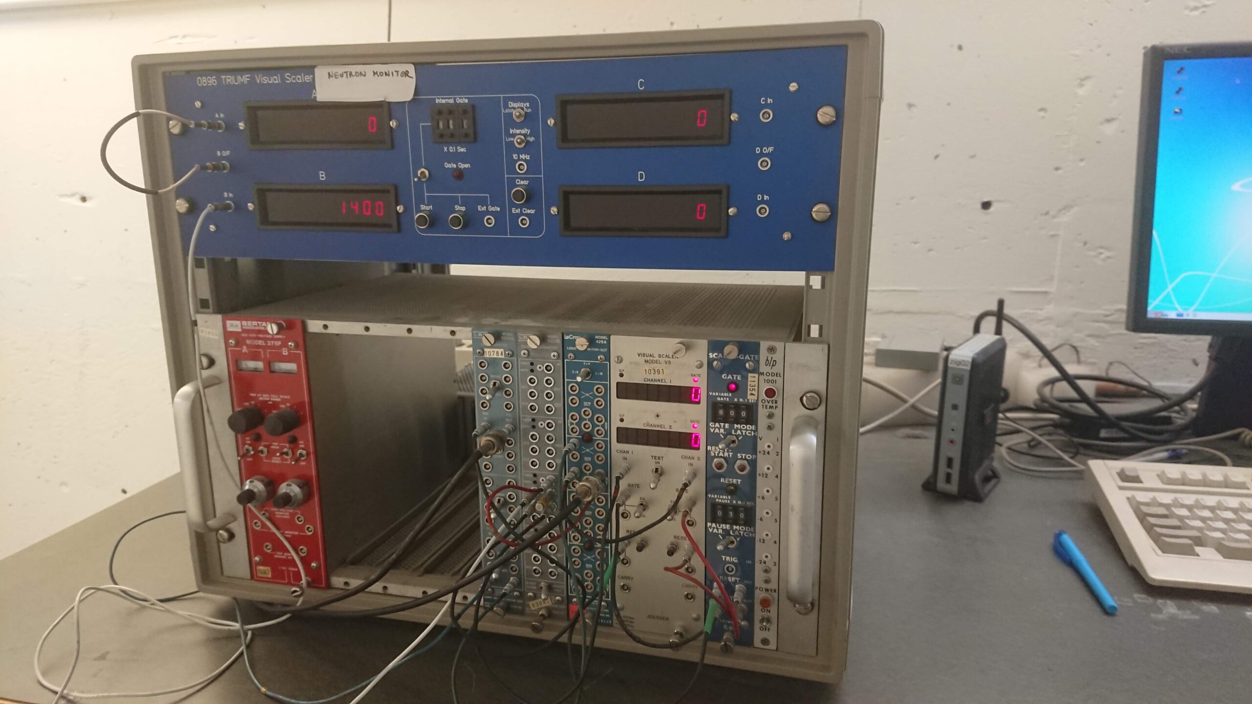
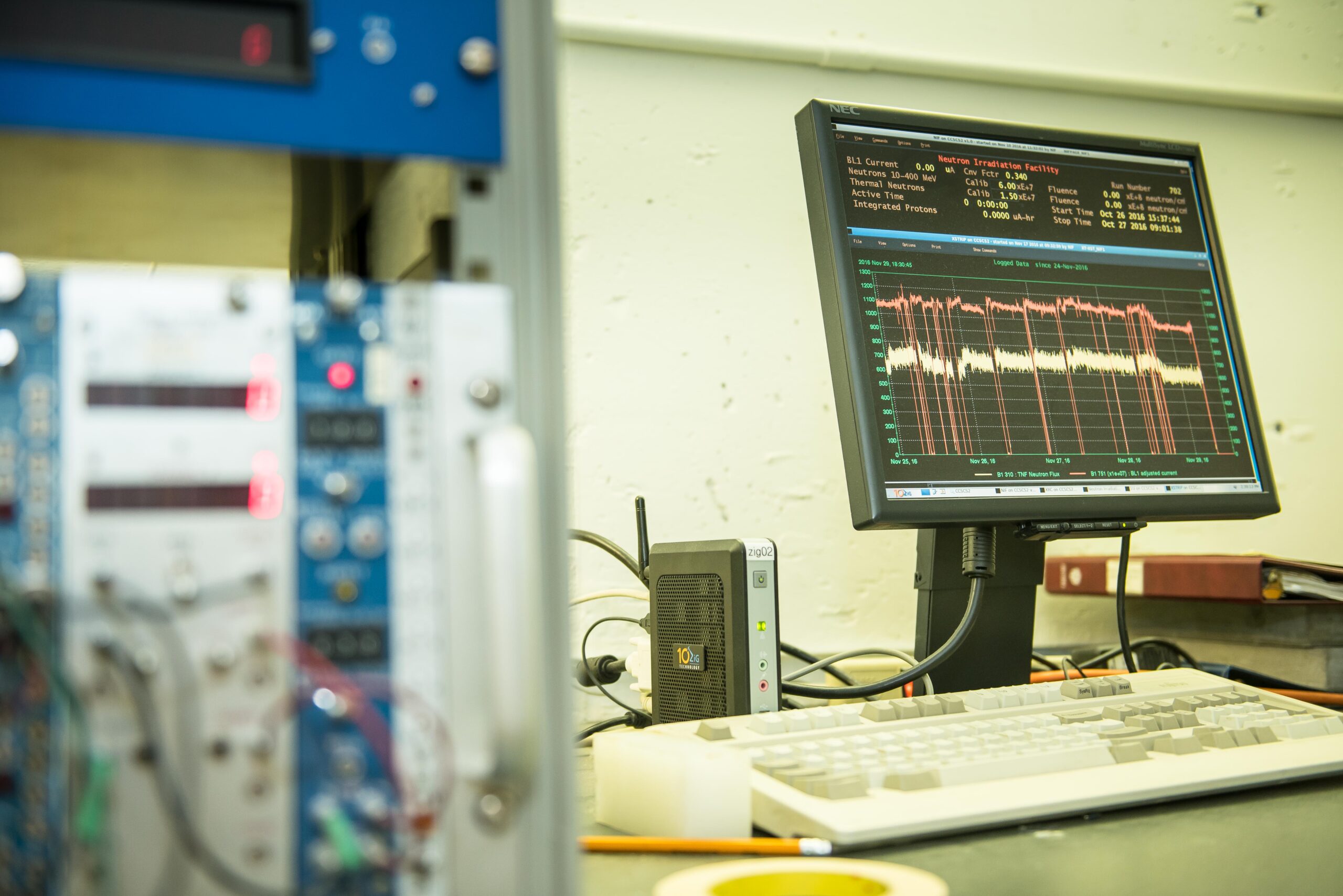
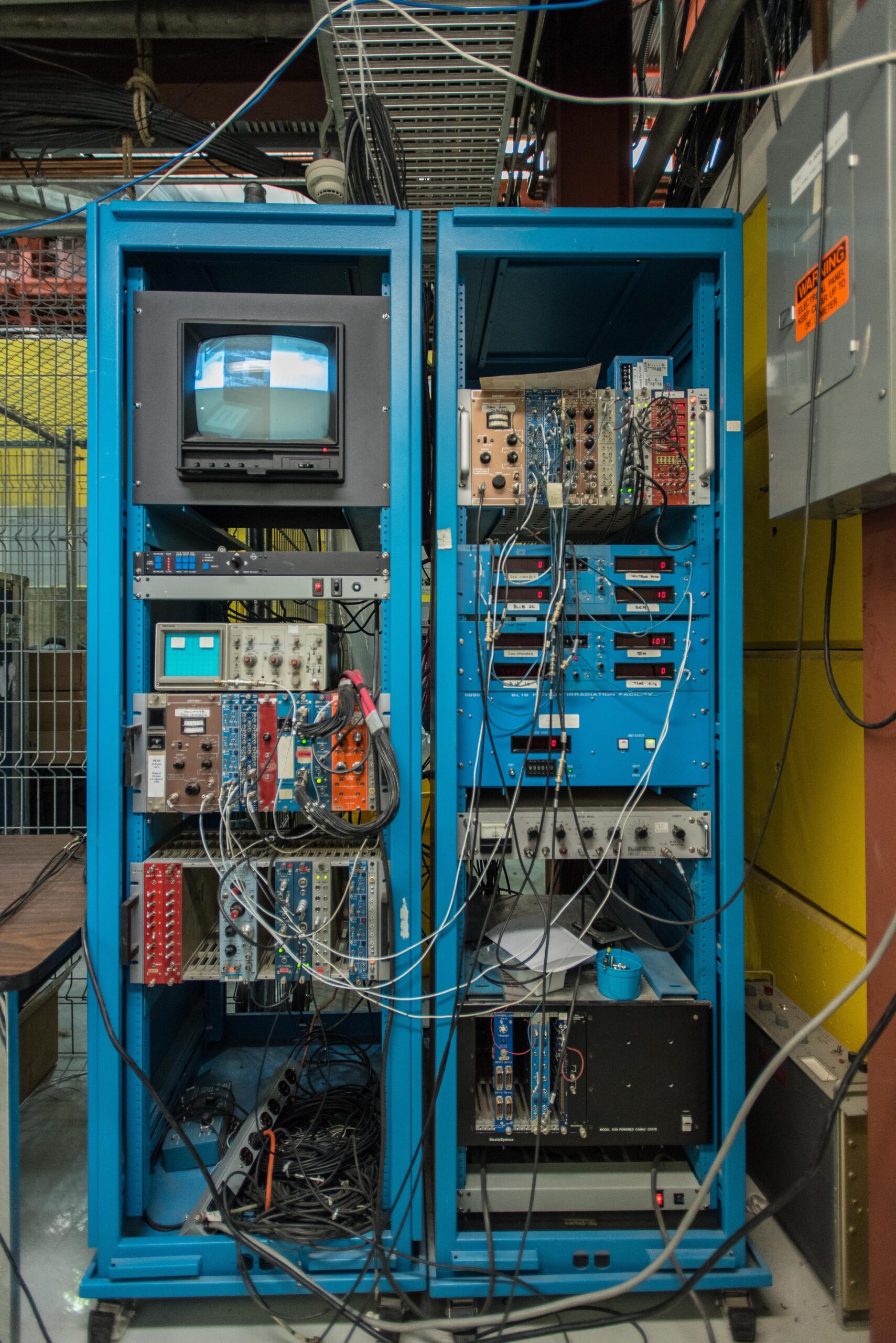
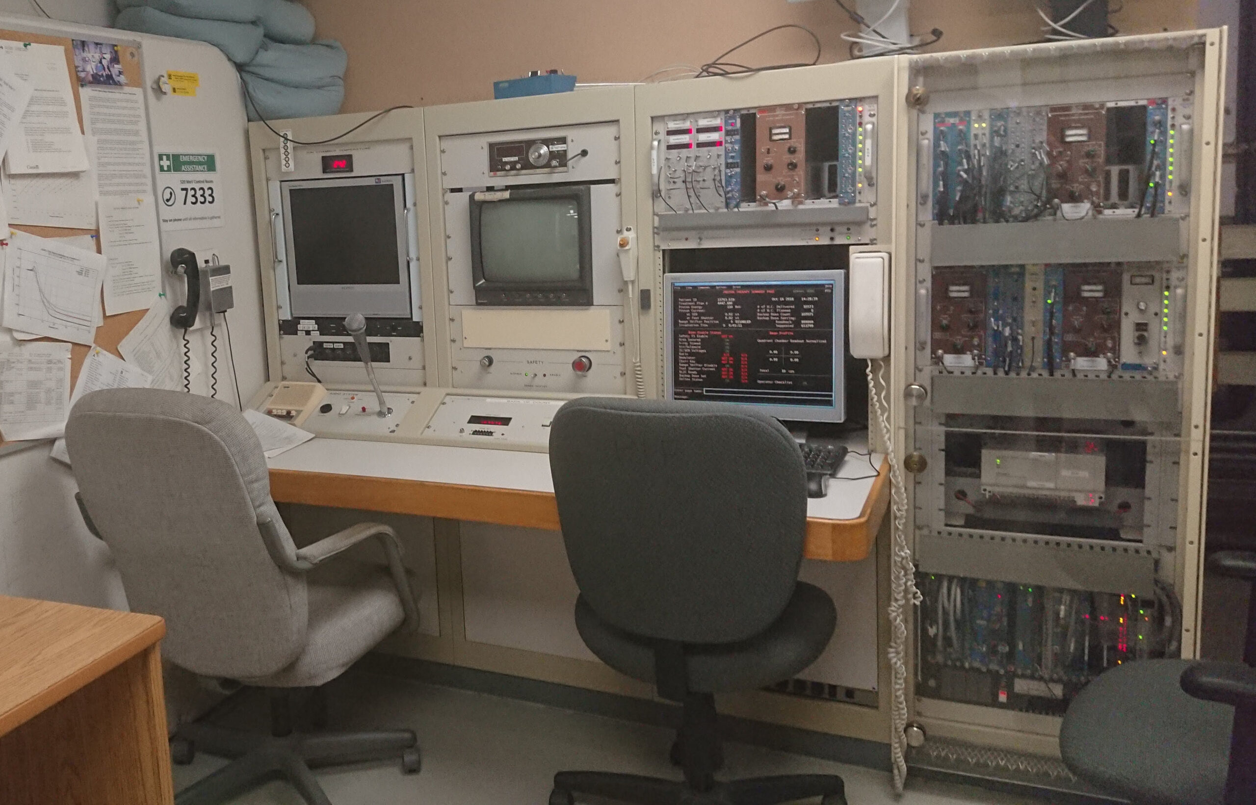
The beam intensity is monitored by an air ion chamber which has been calibrated against plastic scintillators or a miniature calibrated ion chamber. Beam profiles are monitored by an integrating multiwire chamber and there are dedicated electronics and data displays in the Control Area.
|
|
BL1B protons | BL2C protons |
| Standard Test Energies |
350 or 480 MeV (480 MeV preferred) |
63 or 105 MeV Other energies available with a degrader or by changing the cyclotron extraction energy |
| Extracted Intensity | 0.1 to 3 nA | 0.1 to 7 nA |
|
Flux (protons/cm²/s)
|
Standard location: 10⁵ to 4x10⁷ (10² possible) Upstream location: 7x10⁸ max |
Standard location: 10⁵ to 1x10⁸ (10² possible) Upstream location: 2x10⁹ max |
| Spot Size |
Standard location: 3x3 cm to 7.5x7.5 cm Upstream location: 1 to 2 cm diameter |
Standard location: 1x1 cm to 5x5 cm or 7.5 cm diameter Upstream location: 0.5 to 2 cm diameter |
| Spot Homogeneity |
Standard location: +/- 5% Upstream location: +/- 10% |
Standard location: +/- 5% Upstream location: +/- 10% |
| Dose Rate |
Standard location: 10 to 20 mGy/s (1 to 2 rads/s) Upstream location: up to 500 mGy/s (50 rads/s) |
Standard location: 50 to 100 mGy/s (5 to 10 rads/s) Upstream location: up to 1000 mGy/s (100 rads/s) |
| Beam Counting and Monitoring System |
Ion Chamber or Scintillator |
Ion Chamber, Scintillator, or Faraday Cup |
| Device-Positioning System |
Remote-controlled X-Y platform with laser alignment |
Remote-controlled X-Y platform with laser alignment |
| Access Conditions |
22 m cable length to Control Area |
22 m cable length to Control Area |
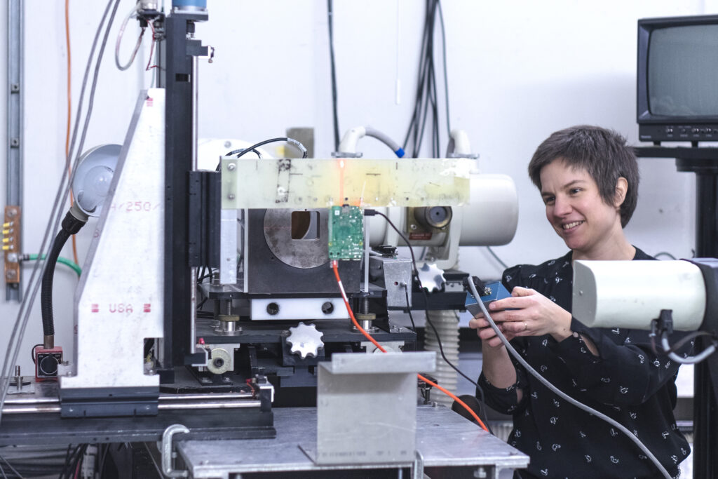
PHOTOS
TNF experimental area
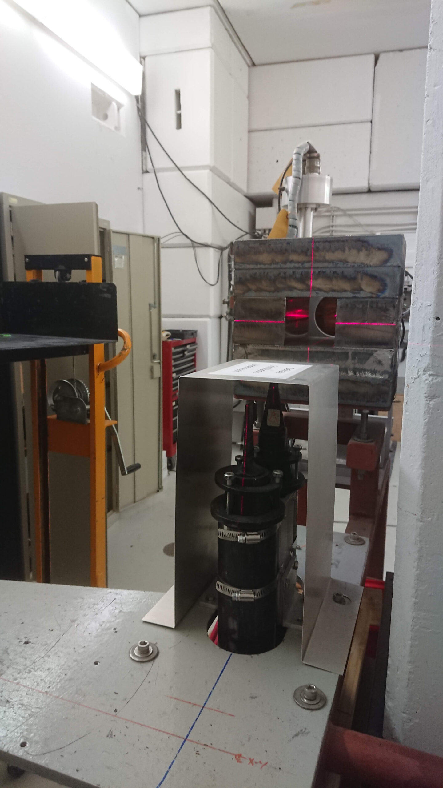
Proton Irradiation experimental area
Overview of beam room and general beamline arrangements
Beamline 1B – details
Beamline 2C – details
Moveable test table
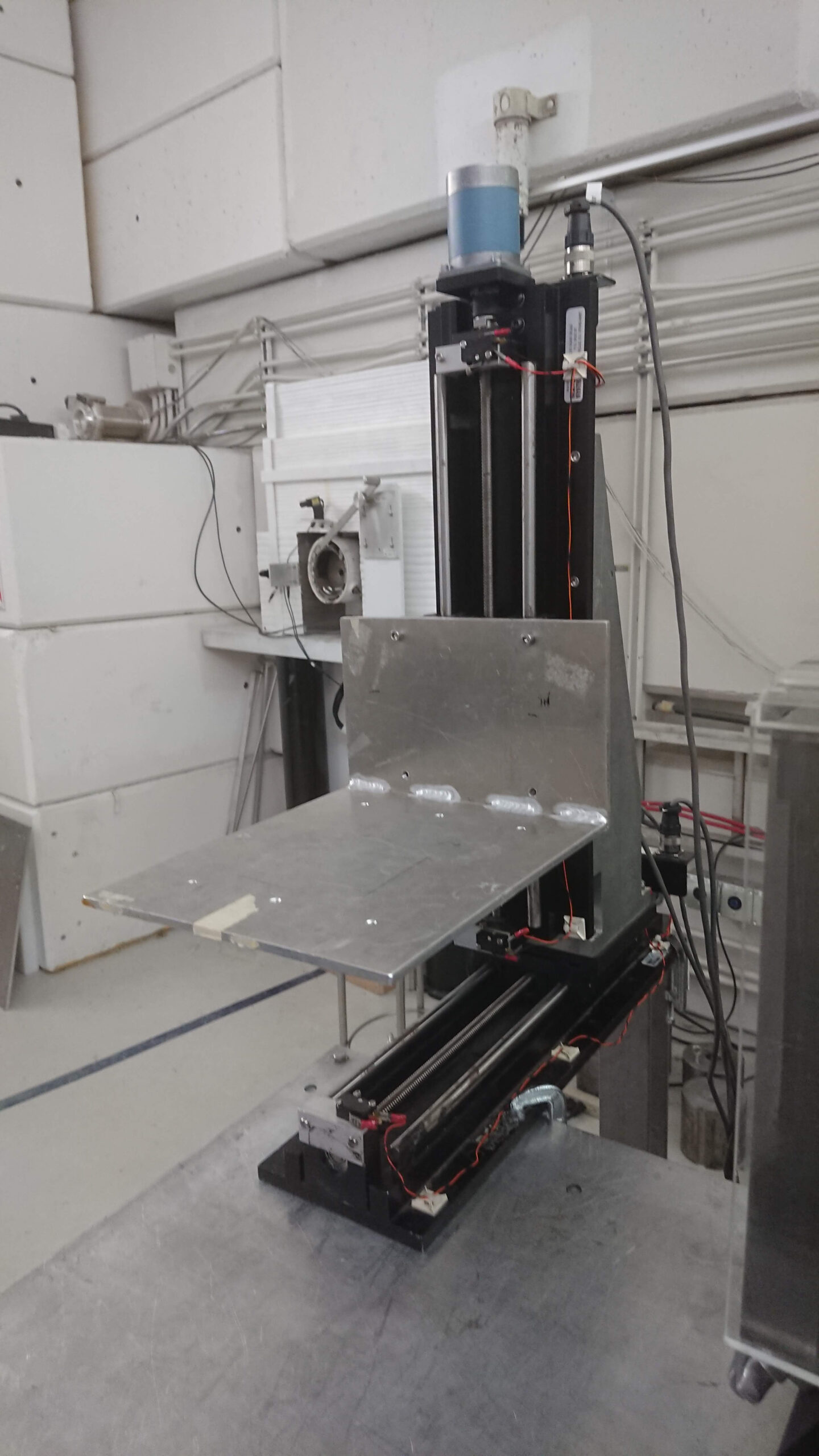
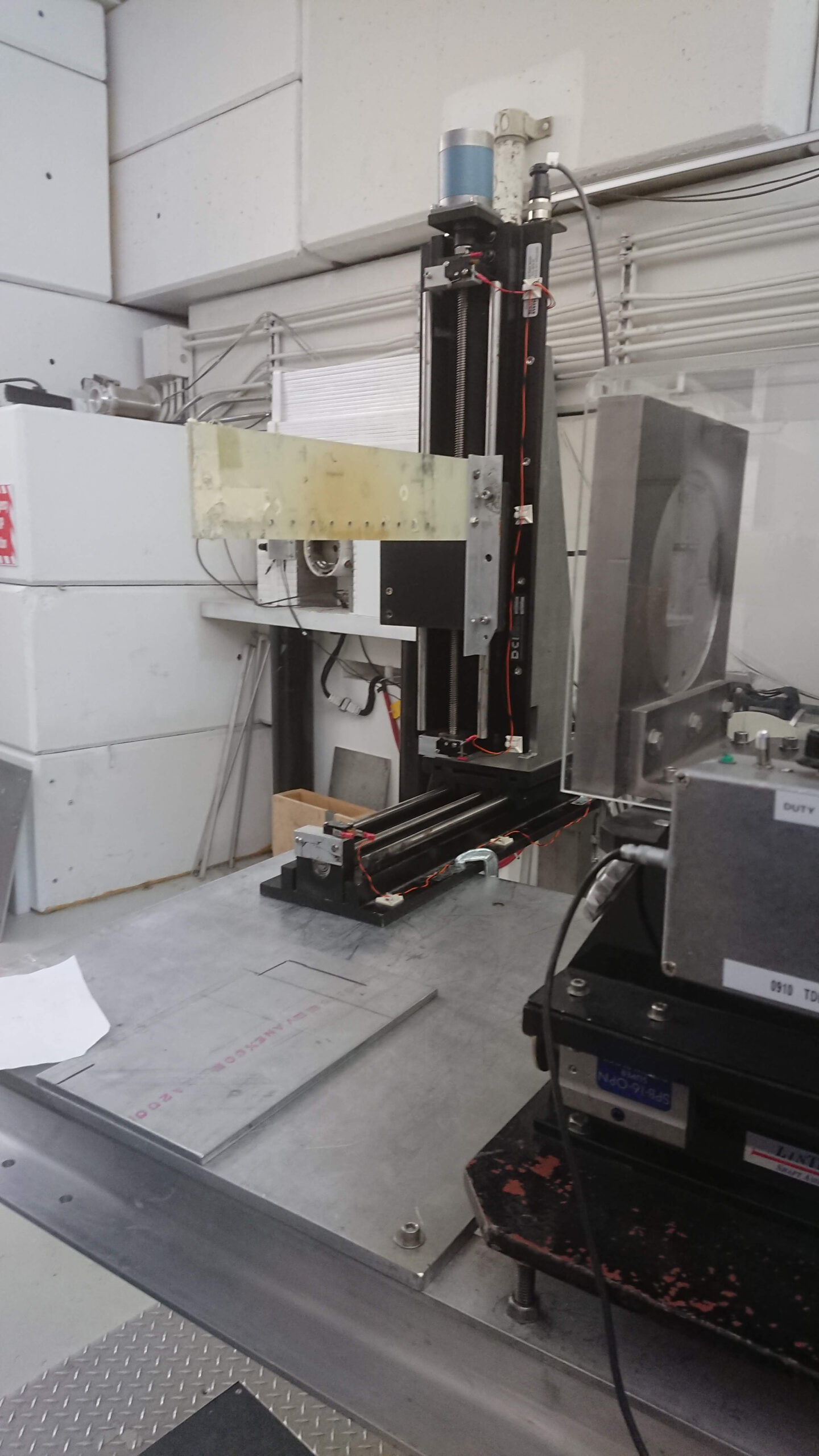
This table can be controlled remotely and the total travel distance is 30 cm both vertically and horizontally
CONTACT INFORMATION
For further information, please contact:
| Michael Trinczek TRIUMF Tel: 604.222.7530 Fax: 604.222.1074 |
Camille Bélanger-Champagne TRIUMF Tel: 604.222.7706 Fax: 604.222.1074 |
Alex Hands TRIUMF Tel: 604.222.7628 Fax: 604.222.1074 |